Electronic equipment is often designed with built-in circuit protection. The main function is to provide protection to both the equipment and the equipment operator in the event of a circuit overload. This protection usually comes in one of two forms: a circuit breaker or a fuse. A circuit breaker is an automatic switch that prohibits the flow of electric current when it is rapidly overloaded or unusually stressed. A fuse is a safety device that protects an electric circuit from excessive current.
5a fuse
Fuse
- Definition of a Fuse
A fuse is a replaceable circuit protection device that provides protection to both the equipment and the equipment operator in the event of a circuit overload. In simplest terms, it is two metal caps with a wire or strip in-between. This is enclosed in a glass or ceramic tube and may be filled with sand for some specialized fuse types. - Function of a Fuse
A fuse is a built-in weak link in an electric circuit that provides overcurrent protection in a piece of equipment. The essential component in a fuse is a metal wire or strip that will melt when the current exceeds the amount that the fuse is designed to withstand, opening the circuit path, and disconnecting the equipment from the power source. When a traditional fuse disconnects or “blows” it must be removed and replaced with a new fuse. - Construction of a Fuse
Typically fuses are constructed using a thin metal strip or filament sheathed in either a transparent glass or ceramic tube. The metal strip is attached on each end to a separate terminal on the outside of the fuse called an end cap. Some specialized end caps have a length of wire attached to each end called axial leads. These are used for soldering directly to a circuit board. The end caps on standard fuses mate with matching terminals attached to the protected circuit. Any current that moves through the circuit flows through the metal inside the fuse. If the metal overheats, it will melt, breaking the electrical connection. Some fuses are filled with sand on the inside. This sand acts as a protective barrier to prevent the fuse from shattering and spreading debris when it blows due to a severe overload event. These are referred to a high-breaking capacity fuses. - Sizes and Characteristics of Fuse
It is important to note that while the terminology is similar for North American and international fuses, the actual characteristics are usually quite different, due to the differences in standards to which the fuses are built.
For North American fuses, the breaking characteristics are defined as “fast-acting” and “time-delay.” Both versions come in either a standard glass, low-breaking capacity construction or in a sand-filled ceramic, high-breaking capacity construction. The North American fuses come in two sizes: ¼ x 1¼ inch or
5 x 20mm. Standards to refer to include: UL 248-1 and CSA 22.2 no. 248.1.
International fuses have similar designations. They are available in “quick-acting/low-breaking” capacity, “time-lag/low-breaking” capacity and “quick-acting/high-breaking” capacity. These fuses have both fast and slow-breaking times. The high-breaking capacity fuses are ceramic/sand-filled. International fuses only come in the 5 x 20mm size. The standards covering international fuses are IEC 60127-1 and IEC 60127-2 and for fuse holders it is IEC 60127-6.
While there are many different kinds of fuses available, these are the ones that Interpower offers.
- North American—¼ x 1¼ inch and 5 x 20mm
Breaking Characteristics (Fast-Acting and Time-Delay):
- Fast-acting
A fast-acting fuse will open on overload and short circuits very quickly. These fuses are used in equipment where there are no transient in-rush currents. They offer protection for equipment that cannot withstand current overloads, even briefly. Fast-acting fuses are typically constructed with a single strand of wire or strip of metal.
Examples of North American Fast-Acting Fuses
Fast-Acting ¼ x 1¼ Inch Glass FuseFast-Acting ¼ x 1¼ Inch Ceramic FuseFast-Acting 5 x 20mm Glass Fuse
P/N: 813AGC-1
P/N: 813ABC-1
P/N: 813GMA-1Fast-acting ¼ x 1¼ inch glass fuses—Different varieties available; all with a rated current ranging from 1/8A to 6A, a voltage rating of 250VAC, and a breaking capacity of either 35A, 100A, 200A or 10000A.
Fast-acting ¼ x 1¼ inch ceramic fuses—Different varieties available; all with a rated current ranging from 1/2A to 20A, a voltage rating of 250VAC, and a breaking capacity of either 35A, 100A, 200A, 750A, or 1500A.Fast-acting 5 x 20mm glass fuses—Different varieties available; all with a rated current ranging from 1/4A to 8A, a voltage rating of either 125VAC or 250VAC, and a breaking capacity of either 35A, 100A, 200A or 10000A. - Time-delayTime-delay fuses are designed to withstand a heavy amount of current overload for a limited amount of time. They are used in equipment that can sustain a brief overload situation; typically where the loads are inductive, such as equipment utilizing fans, transformers, etc. The construction of time-delay fuses usually utilizes a coiled wire, a thick filament wrapped in wire, or a spring for the element.
Examples of North American ¼ x 1¼ inch Time-Delay Fuses
Time-Delay Glass FuseTime-Delay Ceramic Fuse
P/N: 813MSL-1
P/N: 813MDA-1Time-delay glass fuses—Different varieties available; all with a rated current ranging from 1/4A to 8A, a voltage rating of 250VAC, and a breaking capacity of either 35A,
100A, or 200A.
Time-delay ceramic fuses—Different varieties available; all with a rated current ranging from 1/2A to 20A, a voltage rating of 250VAC, and a breaking capacity of either 35A, 100A, 200A, 750A, or 1500A.
- Fast-acting
- International—5 x 20mm
Breaking Characteristics (Quick-acting/Low-breaking capacity, Time-delay/Low-breaking capacity, Quick-acting/High-breaking capacity):
- Quick-acting
Similar to fast-acting, this fuse blows very quickly when overloaded. - Time-delay
Similar to time-delay, the fuse allows the overload to exist briefly before blowing. - Low-breaking capacity
A minimal ability of the fuse to remain physically intact when overloaded. A low-breaking capacity fuse is readily subject to being physically destroyed if the current surge is great enough. - High-breaking capacity
A high level of ability of the fuse to remain physically intact even when the overload is great. The fuse is usually constructed with a ceramic body, rather than glass, and filled with silica sand to absorb a large overload and protect the fuse itself.
Examples of International Fuses
Quick-Acting/
Low-BreakingTime-Delay/
Low-BreakingQuick-Acting/
High-Breaking
P/N: 81411101P/N: 81412161
P/N: 81413421Quick-acting glass fuses—Different varieties available; all with a rated current ranging from .032A to 10A, a voltage rating of 250VAC, and a breaking capacity of either 35A low breaking, 40A, 50A, 63A, or 100A.Time-delay glass fuses—Different varieties available; all with a rated current ranging from .063A to 10A, a voltage rating of 250VAC, and a breaking capacity of either 35A low breaking, 40A, 50A, 63A, or 100A.Quick-acting brass ceramic—Different varieties available; all with a rated current ranging from 1A to 10A, a voltage rating of 250VAC, and a breaking capacity of 1500A high breaking.
- Quick-acting
- United Kingdom—BS 1362
Characteristics:
- Fast/medium clearing speed, high-breaking capacity
Example of a UK Fuse
Tube Ceramic
P/N: 81400990Tube ceramic fuses—Different varieties available; all with a rated current ranging from 3A to 13A, a voltage rating of 240VAC, and a breaking capacity of 6000A.
This fuse is specifically for use in British plugs, not for equipment applications.
- Fast/medium clearing speed, high-breaking capacity
- North American—¼ x 1¼ inch and 5 x 20mm
Fuse Carrier Product Line
Fuse Holder and Fuse Carrier
A fuse holder is mounted in the equipment and is designed to hold the fuse. Fuse holders can hold both North American and international sized fuses. This is based on which fuse carrier is being used. Interpower offers panel-mount fuse holders.
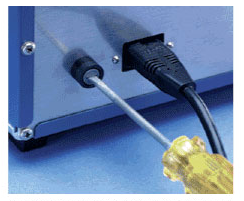
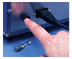
International “touchproof” fuse holders are a popular choice. This type of fuse holder is available in low-profile, high-profile, and low-profile/snap-in versions. Each of these are available with a variety of terminal styles including quick disconnect, solder/quick disconnect and angled versions of both. Interpower fuse holders will also accept both North American and the international fuse carrier and can be used in nearly every market worldwide. These fuse holders offer the additional benefit of being touchproof, providing more safety to the end user—the blown fuse can only be accessed from the outside of the equipment with the use of a tool and cannot touch any of the contact surfaces before the fuse carrier and fuse is removed.
Approvals are available on fuse holders.
Two Examples of a Fuse Holder Offered by Interpower
“Touchproof”/High Profile “Touchproof”/Low Profile
P/N: 80910070
P/N: 80920110
Fuse holder is accessible with a tool only
Contacts are recessed and protected
A fuse carrier is the “cap” to the fuse holder. It carries the fuse into the holder and secures the fuse in place. One of the benefits of using a fuse carrier in conjunction with a fuse holder is that they are touchproof.
Two Examples of a Fuse Carrier Offered by Interpower
For ¼ x 1-¼ inch Fuse For 5 x 20mm Fuse
P/N: 80920200
P/N: 80920210
Fuse Clip
A fuse clip is for internal fuses on PC boards. It takes two of the clips for one fuse.
Fuse clips are an alternative to fuse blocks, with many of the same features. Interpower fuse clips come in one size. They are PC-board mounted and accessible only from within the equipment. It has a “stop” on it, to help position the fuse when it is being inserted. No approvals are available on fuse clips, except as part of the finished product. Because they are inexpensive, they are another attractive alternative to post style and PC-board mount fuse holders. If fuse clips are used, the designer must remember that each end is a separate piece. Two clips will need to be ordered for each fuse used.
An Example of a Fuse Clip
PC-Board Mount with Solder Pins
P/N: 8091A3399-10
Design Strategies
The following are some factors to consider when designing with fuses and fuse holders in mind. The variety of factors dictates that a wide range of fuse sizes and types are available to handle circuit protection, as well as different styles of fuse holders for incorporating the fuse into a circuit. Design considerations must take into account both the fuse and fuse holder together to ensure a suitable pairing is selected. These include:
- What size fuses would be most appropriate?
- What are the load ratings for where the product is being used?
- Does the equipment have a large in-rush at start-up?
- How long can the equipment handle an overload?
- Is the overload large enough to physically destroy the fuse?
- Thermal considerations:
- Power dissipation of the fuse link
- Ratings of the fuse holder
- Ambient temperatures inside and outside equipment
- Electrical load changes
- Long operation times
- Ventilation, cooling, and heat dissipation
- Wire lengths and sizes
- Power dissipation of the fuse link
Fuse Sizes
- Option 1
It is possible to design a product for most markets and specify the common (larger) North American fuse. This will simplify the design process and eliminate inventory problems such as multiple fuse sizes and fuse holders. The downfall is that the global customer will find the North American fuse difficult to source and replace when a failure occurs. Of even greater concern, the North American fuse will not carry any international approvals, as are usually required. These two shortcomings make this strategy unattractive. - Option 2
An alternative strategy might be to specify the smaller 5 x 20mm fuse. This strategy offers the ease of carrying only one size fuse and fuse holder. It also allows the fuse to be positioned in a slightly smaller space inside the equipment, when a design finds space at a premium. The smaller fuse is also more likely to be compatible with a variety of other components, such as multi-function modules.
While the fuse size remains constant under this strategy, it is important to remember that separate fuses for North America and international markets are still required, due to the different approvals. No one fuse carries all of these approvals; the size is the only real constant. Each market has different time-current characteristics for their fuses, based on the approval requirements for the fuses. Since the fuses all have nearly identical appearance, it is quite possible to confuse them. The only real difference is the marking on the fuse caps, which may be difficult to read. It is also worth noting that the 5 x 20 mm fuse, while accepted more often in North America, is not as particularly common as used in North American markets. - Option 3
A third option would be to design a product that accommodates either the international size or the larger North American size fuse. Interpower offers fuse holders that will accept both sizes of fuses. This is accomplished by switching the fuse carrier that fits inside the fuse holder. This strategy allows the end design to be user friendly in all markets, as the user will be able to source replacement fuses. It also ensures the component will be compliant regardless of the market in which it will be used, since the necessary approvals will be in place.
Load Rating Considerations
It is necessary to know the load ratings and surge current characteristics for the equipment in order to choose the appropriately rated fuse, in order to eliminate nuisance fuse blows due to in-rush currents and other current variances due to normal operation, but still adequately protect the equipment and user from genuine fault currents.
The surge current characteristic of the product requires special attention when specifying a fuse. If the product includes motors, transformers, incandescent lamps and/or capacitive circuits, then transient surges, such as in-rush currents, lock rotor currents, or capacitor charging surges must be considered.
In-rush currents can require fast-acting or quick-acting fuses to be sized from 1.5 to 3 times the full steady-state load current. Even after applying this rule of thumb, surge currents could still cause nuisance openings of the fuse, requiring a further increase in fuse size. Time-delay or time-lag fuses might be more appropriate in this situation. With these types, a fuse rating of 1.25 to 1.5 times the full steady-state load current should be adequate to avoid nuisance openings. In this case, the time-delay or time-lag fuse gives the product more protection because its rating can be closer to the full steady-state current. For products with surge currents that are 10 times the full steady-state current during the first 10 milliseconds of operation, or for products that have very little surge characteristics and that may be very sensitive to fault currents, use fast-acting or quick-acting fuses to provide a higher level of protection. In order to verify fuse performance matches known as start-up conditions, use the time-current graphs provided for specific fuses to make the most precise selection of a fuse type and current rating for a given application.
Current ratings of fuses selected not only needs to take surge current characteristics into account, but also needs to take manufacturer’s specified overload current into account for such items as semiconductors, resistors, transformers, or heaters. The selected fuse should be lower than the lowest overload current of the components in a product.
While many products have a steady-state current rating that can be used to help select the correct fuse amperage, some products, such as devices that have motors that are turned on and off, will draw different amounts of current under different operating conditions. In these cases it is important to determine the dynamic current characteristic so that the full load current can be identified.
The safety agencies have established voltage ratings for the various types of fuses. This rating is not important when the product is operating normally; it comes into play when the fuse tries to open the circuit. The fuse must be capable of keeping the circuit open against the potential of the open-circuit voltage. For this reason, make sure that the fuse voltage rating equals or exceeds the line voltage.
Breaking Capacity Selection
It is important to verify that the fuse that is selected has a greater breaking capacity than the maximum available current that can be supplied to the product. This is an important safety consideration. If the breaking capacity is too low, the fuse could literally explode or create an electric arc of unacceptable duration, causing damage to the equipment or injury to an operator, when clearing a short. The maximum AC short circuit current that can be delivered by the mains depends upon such things as the rating of the distribution transformer, the size of the conductors, and the distance from the transformer to the product. Some miniature glass fuses may have a rating only 10x their rated current, and may be sufficient for many applications. However, if extra protection is needed to ensure damage and the need for clean-up are not needed, then a high breaking capacity fuse may be desired. These miniature fuses typically have a ceramic tube that is filled with sand and surrounds the element. The sand and ceramic ensure that the fuse remains in one piece and does not allow arcing, when clearing a fault current.
Thermal Considerations
When designing a piece of equipment that will utilize fuses and fuse holders, it is critical that the design engineer(s) consider thermal influences, such as ambient temperature and heat rise, in relation to the temperature specifications of the fuses and fuse holders, in order to choose the optimal components for the applications, and possibly expand the design to alleviate problems with heat build-up. The selection of the most suitable fuse and fuse holder combination is of great importance. Among other parameters, the engineer must make sure that the maximum admissible power acceptances and temperatures defined by the manufacturer of the fuse holder are followed.
Factors to Consider Include:
- The influence of the power dissipation in the fuse holder contacts
- Rated power dissipation of the chosen fuse
- Admissible power acceptance, temperature ratings, and operating current of the fuse holder
- Ambient air temperatures both inside and outside of the equipment
- Electrical load alternation
- Long term operation with a load >0.7In
- Heat influences of surrounding components
- Heat dissipation/cooling and ventilation designed into the equipment
- Length and cross section of connecting wires.
- Mounting orientation of the fuse holder
Most manufacturers of fuses and fuse holders offer detailed information regarding the above factors and excellent guidance information regarding making the proper selections.
After evaluating the above influences, a selection can be made on an appropriate fuse and fuse holder combination. It is then recommended to run testing on the chosen devices in the worst case operating conditions to verify the selection. If problems arise indicating excessive heat build-up, a different selection may be needed, or changes in the design may be required to alleviate the problem.
Fuse Accessibility is Limited Under International Standards
Users of fuse holders designed to comply only with UL/CSA requirements are accustomed to a fuse carrier with a knurled cap that makes it easy to access and change a fuse without tools. Various international equipment standards, however, limit the degree of user accessibility to a fuse holder in order to minimize the possibility of electrical shock to a non-technical user. The limited access fuse holder is designed to require the use of a tool (usually a screwdriver). It also incorporates additional insulation and insulating barriers that eliminate the presence of live conducting services during fuse change operations.